3

tl;dr

If one has an angular accelerometer, what is the motion that it actually measures?

If we have a perfect (i.e. noise-free, error-free, perfectly aligned, ...) 3-axis angular accelerometer, given appropriate initial conditions, how does one obtain a SO(3) rotation from the (double) integration of said measurements?


Background and Details

If one were to open practically any inertial navigation textbook, it will describe an angular rate sensor as measuring ${\omega}_{ib}^{b}$ - that is, the angular rate of the the body with respect to the inertial frame, resolved in the body frame axes.

One may obtain a SO(3) rotation matrix from said gyro measurements using well-known differential equation:

$\mathbf{\dot{R} }_b^i = \mathbf{R}_b^i [{\omega}_{ib}^{b}]_\times$

where $\mathbf{R}_b^i$ is the rotation from the body frame to the inertial frame and $[{\omega}_{ib}^{b}]_\times$ is a skew-symmetric matrix constructed from the gyro measurements. The differential equation has a well-known solution for constant angular rate over a sampling interval:

$\mathbf{R}_{b(k+1)}^i = \mathbf{R}_{b(k)}^i \operatorname{expm}(\Delta t [{\omega}_{ib}^{b}]_\times)$

Using similar notation, what would be the quantity that an angular accelerometer measures (e.g. example device)? How do such measurements relate to angular rate measurements? How would one solve this (presumably) differential equation to obtain angular rate and a rotation matrix?

Please note this isn't meant to be a discussion on the practicality of such a solution - the issues are well-known (e.g. see p38 of Lawrence).

(Note to moderators: angular-acceleration would be an ideal tag for the question, but unfortunately no such tag exists)
Damien
  • 191
  • Presumably from your last sentence, this isn't a technology question. Can you not get the manufacturer to answer this? If the output of the sensor is $\dot{\omega}$, then you are simply going to integrate this with the appropriate noise minimizing measures and initial value for $\omega$ to get $\omega(t)$. Then you're either going to use the discretized product of exponentials you cite or Rossmann Theorem 1.5 to integrate $\omega(t)$ to $\alpha(t)$, where the rotation is $\exp(\alpha(t))$ as descibed in my answer here: http://physics.stackexchange.com/a/288904/26076 – Selene Routley Jan 27 '17 at 04:19

1 Answers1

1

What is the Sensor Sensing?

After some thought, here's a guess as to what is happenning.

The most obvious way to measure angular acceleration is in a way analogously with linear acceleration by many accelerometers - through the stresses a change of state of motion induces on a test mass / inertia - and it's a pretty good bet that at least some angular accelerometers work this way.

However, the stresses are not always proportional to the angular acceleration, in contrast with a linear accelerometer, wherein the test mass stresses are directly proportional to linear acceleration. We can, however, with the right symmetry of the sensor, arrange the angular acceleration to be proportional to the stress.

Accelerometer

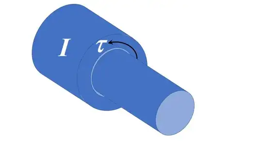
I've sketched the notion of such a device above. The test inertia is a heavy bushing that is sleeved on a shaft, and the change in the bushing's state of motion requires a torque to be transmitted from the inner shaft. You could build a sensor sensitive to the torque component along the shaft's axis by, e.g. stress sensors on the faces of a key / keyway that prevents relative motion between bushing and shaft.

Because the axis of the component is changing, we need to account for the rotating reference frame through, e.g. the Euler equations. We would arrange the axis in the sketch above to be along one of the principal axes of inertia of the bushing (as indeed in it is in the sketch). With $I$ the inertia tensor, the nett torque on the bushing is:

$$\tau = I\,\dot{\omega} + \omega\times (I\,\omega)\tag{1}$$

so that the component of torque along the sensed axis is:

$$\tau_z = I_{zz}\,\dot{\omega_z} + (I_{yy}-I_{xx})\,\omega_x\,\omega_z\tag{2}$$

which is the reason for my comment that the stresses are not always in proportion to the angular acceleration. However, if we arrange the test bushing to be rotationally symmetric about the sensitive axis (as in the sketch), then $I_{yy}=I_{xx}$ and so (2) becomes the convenient equation:

$$\tau_z = I_{zz}\,\dot{\omega_z}$$

so that the sensor output is indeed proportional to the component of the rate of change of $\omega$ in the sensed direction.

But of course the sensed axis is changing direction, so we need to transform the above to non-inertial co-ordinates before integration to the rotation matrix.

Integration to Rotation Matrix

To be continued (when I have worked out my confusion in the relevant frame transformations)