1

A loop is moving down with some part of it in a constant magnetic field pointing into the screen as shown. We know the emf due to magnetic force is given by

$\mathcal{E}=-\frac{d \Phi}{d t}$.

If the loop has a total resistance of $R$ then why is it that the current in the loop will be

$I=\mathcal{E}/R$.enter image description here

Kashmiri
  • 1,220
  • 13
  • 33
  • What else would it be? – jacob1729 Oct 17 '20 at 17:23
  • Ohms law is$I=\frac{V}{R}$ we don't have $V$ here instead it's e which is different from V – Kashmiri Oct 17 '20 at 17:25
  • The emf $\varepsilon = -\frac{d\Phi}{dt}$ provides the potential difference between two points on the loop as it falls through the ${\bf B}$-field. – Physics_Et_Al Oct 17 '20 at 17:28
  • @Physics etal, how? – Kashmiri Oct 17 '20 at 17:29
  • I suggest you go read up on Faraday's law and motional emfs. – Physics_Et_Al Oct 17 '20 at 17:30
  • This equation is used by Griffiths before going to Faradays law in problem 7.11 so I'm sure the answer isn't Faradays law. – Kashmiri Oct 17 '20 at 17:32
  • 1
    Okay, well I'll check Griffith's later as I am a bit busy. As jacob1729 pointed out it can't really be anything other than Ohm's law since the back emf, $\varepsilon$, is produced by the magnetic flux through the loop changing with time as the loop falls. This induces a current in the loop in accordance with Lenz's law. So it cannot really be anything else other than $\varepsilon = IR$. – Physics_Et_Al Oct 17 '20 at 17:38
  • Read sections 7.1.2 and 7.1.3. Perhaps, read all of section 7.1. – Physics_Et_Al Oct 17 '20 at 17:50
  • I've read them over and over again, I'll be grateful if you could point out the proof . – Kashmiri Oct 17 '20 at 17:57
  • You will NOT find a proof of the $i=\mathcal{E}/R$ in any textbook referring to current induced in a closed conductive loop, because that formula does not calculate the correct currents for all values of R. This formula ignores the opposite magnetic flux generated by the current induced in the loop and yields an absurd INFINITE current for any non-zero $\mathcal{E}$ when $R=0$. It also gives erroneous currents for small non-zero resistances. – George Robinson Oct 19 '20 at 22:38

5 Answers5

3

Good question. In my experience, most introductions to E&M don't give a great explanation of the exact similarities and differences between voltage and electromotive force (emf), and when you can and can't use the concepts interchangeably.

Voltage and emf are both formally defined the exact same way, as the (negative) line integal of the electric field over some path: $-\int_A^B {\bf E} \cdot d{\bf l}$. But the terms are used in different contexts. Voltage is used in the electrostatic context, where no magnetic fields change significantly over time and the electric field is generated by fixed electric charges (or chemical potentials, etc.). emf is used in the context of Faraday's law, where the electric field is induced by a time-varying magnetic field. In situations where both source charges are time-varying magnetic fields play a role, the distinction can get a little blurry.

Another difference is that in a magnetostatic situation, the value of the line integral is path-independent and only depends on the endpoints. Therefore, voltage is usually thought of a property relating two points in space, while emf explicitly depends on the path that the wire takes between the endpoints.

But both of them have the effect of pushing current through conductors. You can use emf in the place of voltage in pretty much all formulas regarding DC electric currents through wires, as long as the situation is quasistatic enough that you can assume that the electric field is uniform along the wire (which in practice is almost always the case).

tparker
  • 47,418
  • Thank you, but I was looking for some proof. – Kashmiri Oct 17 '20 at 17:43
  • 2
    @YasirSadiq you have got a cogent explanation, there really is nothing else much to say; if you still do not understand it then read it again, this is Faraday's law and it is not more "provable" than Newton's law $F=ma$. – hyportnex Oct 17 '20 at 18:08
  • 1
    @YasirSadiq It's largely a matter of sorting out what $\mathscr E$ and $V$ actually mean. tparker has done this admirably. – Philip Wood Oct 17 '20 at 19:51
  • @hyportnex and Philip Wood, Thank you. In this case the magnetic emf is present only in the upper wire which is in the magnetic field. So we should have $I=\frac{E}{R / 4}$ if voltage and emf could be replaced here. But instead of having $I=\frac{E}{R / 4}$ we have $I=E/R $ . – Kashmiri Oct 18 '20 at 05:21
  • 2
    @tparker: Notice that the OP asked "why is it that the current in the loop...?" which is a question about the current in the loop. However your answer is predominantly about the induced emf and voltage, as well as the difference between these two terms. – George Robinson Oct 19 '20 at 10:41
1

No proof exists for the combined relation:

$I=-\frac{d \Phi}{d t}/R$

...because it is not true in all cases.

This happens because the current induced in the loop generates it own internal magnetic flux that opposes the external magnetic flux according to the Lenz Law. That reaction modifies the variable $\Phi$ in the equation above.

Consider the limiting case when the resistance of the shorted loop is zero (this can really happen in superconducting loops).

According to that Ohm's Law relation: $I=\mathcal{E}/R$
...any induced $\mathcal{E}$ would generate infinite current in the loop. That would be absurd.

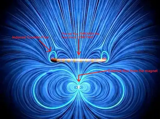
What happens in reality, in such case, is that the SUM of the external flux + the flux generated by the current induced in the loop = CONSTANT.

See this simulation of a R=0 loop moving through the field of a permanent magnet

The simulation above depicts the loop moving over the field of a magnet instead of across a uniform field, but the principle of changing the flux encompassed by the loop is the same.

Counter Flux

The reason for this is that any change in net flux requires a nonzero $\mathcal{E}$ around the loop, which requires an infinite current, so the net magnetic flux through the loop cannot change. The flux from the self-inductance $L$ of the loop must be equal and opposite to the external flux, thus we conclude that in a shorted coil without resistance, the max induced current is INDEPENDENT from $\frac{d \Phi}{d t}$ and simply equal to $I=-\frac{\Phi}{L}$.

  • That is great answer and simulation video. How would you modify the last sentence of your answer for the case where the loop has resistance (not superconducting)? – relayman357 Oct 18 '20 at 13:52
  • If the coil was not purely inductive and had some resistance then I would have to include the continuous dissipation of the induced current in the resistance as heat energy (and the resulting dissipation of the counter-flux, too) as a time integral of the term $Ri^2$ over dt and change the simulation to look like this: https://youtu.be/wUaqXk6axOo . Also I would write that because of this resistive dissipation, the maximum induced current is smaller than in the R=0 case. – George Robinson Oct 18 '20 at 14:15
  • Outstanding, thank you sir. – relayman357 Oct 18 '20 at 14:21
  • 1
    Of course when the mass or weight of the magnet is much larger, then the magnet will not bounce back up - it will just fall through the loop with a little slowdown. The same can happen when the magnet has a smaller flux or the loop is larger with respect to the magnet. – George Robinson Oct 18 '20 at 14:32
  • What package did you use for your simulations? – relayman357 Oct 18 '20 at 14:44
  • EM Works and C++. Below is a simulation of a heavy magnet falling through a superconducting loop without bouncing. https://youtu.be/yMg6j-UoUfo Notice that the net flux through the loop remians constant and that the flux from the magnet never crosses the ring. – George Robinson Oct 18 '20 at 18:33
  • That is fantastic! – relayman357 Oct 18 '20 at 19:35
0

In this situation, there will be a magnetic force acting on the free electrons in the upper segment of the loop, pushing them to the left and producing a potential difference, vBl, between the two ends of that segment. On the other hand, a closed conducting loop totally within a uniform magnetic field which is changing with time will experience an emf which pushes electrons around the loop, but voltage differences will be dissipated from point to point as the current moves through the resistance of the conductor.

R.W. Bird
  • 12,139
  • a potential difference, vBl, between the two ends of that segment can be produced if the electrons are in equilibrium, that is net force on them is zero, but here that isn't the case. – Kashmiri Oct 18 '20 at 05:13
  • The current in the loop will be determined by the total resistance of the loop. I should have noted that some of the potential difference along the upper segment will be lost to the resistance of that segment. – R.W. Bird Oct 18 '20 at 13:26
  • When you write "The current in the loop will be determined by the total resistance of the loop" do you mean this? $I=\mathcal{E}/R$. – George Robinson Oct 18 '20 at 14:21
  • Yes, and in this case ε = vBL – R.W. Bird Oct 18 '20 at 17:25
  • @R.W. Bird: The equation $I=\mathcal{E}/R$ is wrong in the limit as R goes to zero, because at that limit any non-zero $\mathcal{E}$ implies arbitrarily large ('infinite') current. ... which is absurd. – George Robinson Oct 18 '20 at 19:30
  • Real wires have a finite resistance. – R.W. Bird Oct 18 '20 at 19:36
  • Are you claiming that superconducting wires are not real, ...as in fiction? Anyway, if
    your equation fails at the limit, then it also fails when the limit is approached, i.e. for very small resistances that are still greater than zero. In other words, this is not a general equation that reflects reality and as such it is wrong. This error is caused by the ignorance of the opposing magnetic flux due to the current induced in the loop. See https://physics.stackexchange.com/questions/62721/faradays-law-does-the-induced-currents-magnetic-field-affect-the-change-in-f
    – George Robinson Oct 18 '20 at 21:09
  • You are right, I was ignoring the self-inductance of the loop. – R.W. Bird Oct 19 '20 at 13:31
0

If the loop is going down at a velocity $v_y$, for a magnetic field B, loop width $L$, and portion of loop height in the field $= y$, $$\frac{\partial \phi}{\partial t} = \frac{B \partial (Ly)}{\partial t} = \frac{LB \partial y}{\partial t} = LBv_y$$

As you said, an electric field is generated in the conductor:$$E = -\frac{\partial \phi}{\partial t}$$ If the velocity is constant, $E$ is also constant, and we have a static situation: $V = \oint{Edl} = RI$.

If it is not constant, the changing magnetic field generated by the current in the conductor generates an E-field that opposes that current. So, strictly speaking, $V \neq RI$ in this case. In practice that second effect is very small, except for a big indutance and small resistance of the conductor.

Both effects must be evaluated together, what mathematically means that the 2 Maxwell equations:

$$\nabla \times E = -\frac{\partial B}{\partial t}$$ $$\nabla \times B = \mu_0j + \mu_0 \epsilon_0 \frac{\partial E}{\partial t}$$

have to be fulfilled simultaneously for the total fields.

0

Ohm's law in the form

$$ I = \frac{V}{R} $$ where $V$ is voltage between two points, is merely a special case of general Ohm's law applicable only to situations where all electromotive forces active in the metal conductor are due to electrostatic field. This is not the case here, as the current is not due to electrostatic field, but due to special electromotive force of the conductor itself acting on the mobile charges forming the current, called motional EMF. It appears whenever conductor moves in magnetic field.

General Ohm's law (ignoring magnetic forces) is $$ \mathbf E + \mathbf E^* = \sigma \mathbf j $$

where $\mathbf E$ is total electric field, $\mathbf E^*$ is total non-electric force per unit charge (in this case, force due to the wire moving in magnetic field).

We can integrate both sides of the general Ohm's law for some segment of the circuit in the following way:

$$ \int_{start~of~s}^{end~of~s} (\mathbf E + \mathbf E^*) \cdot d\mathbf s = \int_{start~of~s}^{end~of~s} \sigma \mathbf j \cdot d\mathbf s $$ The left-hand side is called total electromotive force for segment $s$ and we can denote it $\mathscr{E}_s$.

If we imagine the circuit wire is torus of cross-section area $A$ and length $L$, we can do the integration over the whole closed circuit, and then we get

$$ \mathscr{E}_{circuit} = \frac{\sigma A}{L} I. $$

We know from high school that ohmic resistance of circuit is $$ R = \frac{\sigma A}{L} $$ so we finally arrive at the equation

$$ \mathscr{E}_{circuit} = RI. $$

This is the other (integral) form of the general Ohm's law.