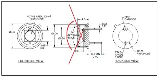
The following diagram is for a photodiode:
 https://www.mouser.ca/datasheet/2/313/firstsensor_PC10-2-TO5-1196700.pdf
I ran through the geometry for photodiodes using the window dimensions, die dimensions, distance of of the die to the window, and the "ray" lines indicated by the datasheet. I did this for three photodiodes and every time I came up with an angle rather closely to that listed in the datasheet so it does not seem like it is a coincidence.
For example:
- 64 Degrees Listed, 68 Degrees Calculated
- 91 Degrees Listed, 84 Degrees Calculated
- 100 Degrees Listed, 95 Degrees Calculated
Note that this FOV of view is defined by the 50% sensitivity cutoff (something completely unaccounted for in the trigonometric method I used) and the curve for the sensitivity vs angle isn't necessarily a cosine centered on the active area. There's also diffraction and other effects going on here.
My question is why do those ray lines seem to be chosen for the first order approximation? (i.e. the ray line from the edge of the die's active area to the nearest window edge). Because it seems to make intuitive sense to me that the ray line that traces out the field of view should be from the edge of the die's active area to the opposite opposite far edge of the window as indicated by the red lines, rather than the ones that are actually used.