1

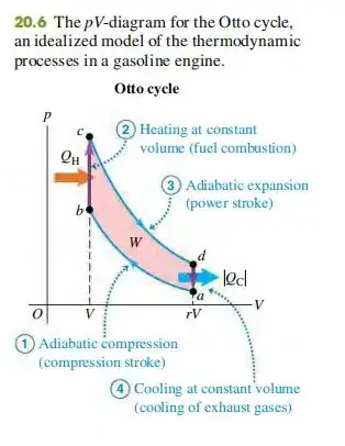
In an IC engine, the air fuel mixture is ignited in a cylinder resulting in temperature rise of the mixture. However, there is no heat flowing into the engine cylinder from some heat reservoir. Yet, in the P-V graph below, it says that heat $Q_H$ is flowing into the cylinder.

Question: From what heat reservoir is $Q_H$ coming?

PV graph in IC engine

Sunil
  • 217
  • 1
  • 2
  • 8

2 Answers2

3

The part of the cycle where the red arrow is pointing is the 'ignition'.

That's when the new fuel/air mixture taken into the engine is ignited and provides the energy input. So the heat comes from the ignition of the new fuel.

John Hunter
  • 13,700
  • Normally heat energy is something that flows across boundaries. But here what's the boundary for heat flow? – Sunil Oct 03 '21 at 10:15
  • 1
    @ Sunil, yes it's different to many thermodynamic applications, but here the fuel is injected into the cylinder, so maybe that's the point where you could say it crosses the boundary from outside the engine to inside. The fuel has potential chemical energy in it, then when ignited it becomes heat energy. – John Hunter Oct 03 '21 at 10:17
  • So, the fuel air mixture after ignition becomes the heat reservoir? – Sunil Oct 03 '21 at 10:23
  • 1
    @ Sunil yes, you could describe it that way – John Hunter Oct 03 '21 at 10:24
  • I had someone tell me that in an IC engine the chemical energy is being directly converted to internal energy without any heat energy being involved. But all books I have come across mention $Q_H$ as heat inflow. So, I doubted if above statement of chemical energy to internal energy conversion is happening. – Sunil Oct 03 '21 at 10:36
  • 1
    @ Sunhil perhaps you could look at this question https://physics.stackexchange.com/questions/86924/is-thermal-heat-energy-the-same-thing-as-internal-energy about the difference between heat and internal energy. Technically the ignited fuel suddenly has more internal energy (kinetic energy), then that energy (by heat flow) spreads to the rest of the mixture in the cylinder, the air and any spent fuel/air mixture that was not fully removed at the exhaust part of the cycle, that's the best I can do, hope you find a way to make sense of it all! – John Hunter Oct 03 '21 at 10:53
  • It would be good to add the above content to your answer so that $Q_H$ concept is made clear since there is no external heat reservoir supplying this $Q_H$. So, it seems that heat reservoir is created within the cylinder as a consequence of combustion. – Sunil Oct 03 '21 at 11:27
  • Please tell me you don't think that that tiny amount of energy released by the spark is what the QH is supposed to represent. In the IC engine, the combustion step takes place essentially adiabaticly. The QH in the figure is introduced to "simulate" the effect of the internal energy change due to chemical reaction $\Delta U_R$. The figure is not a truly correct representation of an IC cycle which involves a combustion step in which $Q_H=\Delta U=\Delta U_R+C_v\Delta T=0$ such that, in the combustion step $\Delta T=(-\Delta U_R)/C_v$. – Chet Miller Oct 03 '21 at 15:07
0

The diagram in the figure does not really represent the version of the Otto Cycle in an IC engine. It "simulates" this using what they call in the literature the "standard air Otto cycle." (Fundamentals of Engineering Thermodynamics, Moran et al; Introduction to Chemical Engineering Thermodynamics, Smith and Van Ness). In the IC version of the Otto cycle, there is no QH added in the first step, and energy is released to the gas by chemical reaction. In the standard air version of the Otto cycle, heat QH is added to an inert gas (air) to simulate the energy released by the chemical reaction.

The first law analysis of the IC version of the Otto cycle goes like this: In the first step, the system is adiabatic and isochoric, such that $$Q = W = \Delta U = 0$$In addition, for the ideal gas mixture that experiences the combustion reaction, the change in internal energy per unit mass is related to the internal energy change of reaction (per unit mass) by $$\Delta U=\Delta U_R+C_v\Delta T$$where $\Delta U_R$ is the internal energy change per unit mass in going from combustion reactants to combustion products at constant temperature. If we combine these two equations, we obtain: $$\Delta T=\frac{(-\Delta U_R)}{C_v}$$which, for an exothermic reaction is positive.

The first law analysis of the standard air version of the Otto cycle goes like this: In the first step, the system is isochoric, but receives heat $Q=Q_H$ from the surroundings, such that $$\Delta U=C_v\Delta T=Q_H$$So in this version of the process, neither the heat added nor the internal energy change is zero. From this equation, it follows that $$\Delta T=\frac{Q_H}{C_v}$$

Comparing these two versions of the Otto cycle, we see that the standard air version can be made to simulate the actual IC version of the cycle if we specifically choose $Q_H$ for the standard air version such that $$Q_H=-\Delta U_R$$
Chet Miller
  • 33,586
  • 3
  • 21
  • 48