I'll answer the first question: In-Axis holography refers to objects placed within or nearby an axis normal to the holographic plate. This is usually refered as Gabor's architecture. Off-Axis holography removes the problem of ghost images placing the object outside the normal. It was firstly introduced by Leith-Upatnieks. Let's first consider the holographic record of a point source:
Let $\psi_0$ represent the field distribution of the object wave in the same plane as the holographic plate. Similarly, let $\psi_r$ represents the reference wave. The holographic plate is sensible to incoming intensity, therefore its amplitude transmittance is:
$$
t(x,y) \propto |\psi_0 +\psi_r|^2
$$
Let's consider an off-axis point source at distance $z_0$ from the holographic plate. According to Fresnel's diffraction, the object wave emerges from the point source and reaches the plate as a diverging spherical wave:
$$
\psi_0=\delta(x-x_0,y-y_0) \ast h(x,y;z_0)= \exp(-i k_0 z_0) \frac{ik_0}{2\pi z_0} \exp(-i k_0 [(x-x_0)^2+(y-y_0^2)] / 2 z_0)
$$
where h(x,y;z) is a simplified impulse response function solution to the Green problem for Fresnel diffraction. The simplification consist on taking the paraxial approximation and observing the field at a distance $z>>\lambda_0$.
Let's $\psi_r$ be a plane wave whose phase is the same as the object wave at $z_0$. Therefore, the reference wave field distribution is $\psi_r= a \exp(-i k_0 z_0)$. Thus, intensity distribution recorded at the plate (hologram's transmittance) is:
\begin{equation}
t(x,y) \propto |\psi_0 +\psi_r|^2
\end{equation}
$$
=\left|a + \frac{i k_0}{2 \pi z_0} \exp(-i k_0 \left[(x-x_0)^2+(y-y_0^2)\right] / 2 z_0)\right|^2\\ = a^2+\left(\frac{k_0}{2\pi z_0}\right)^2 + \frac{k_0}{2\pi z_0} \sin\left(\frac{k_0}{2 z_0} \left[(x-x_0)^2+(y-y_0^2)\right]\right)\\=FZP(x-x_0, y-y_0;z_0)
$$
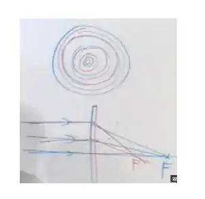
This functions are called sinusoidal Fresnel Zone Plates and they look like this:

The center of the FZP specifies localization of the point source: $x_0$ e $y_0$.
Spatial variation of the FZP is governed by a sinusoidal function with a quadratic spatial dependence. Now let's place the point source on-axis: $x_0=y_0=0$, at some distance $z_0$ from the plate:
$$
t(x,y) \propto |\psi_0^2 +\psi_r^2|^2
$$
$$
=\left|a + \frac{i k_0}{2 \pi z_0} \exp(-i k_0 (x^2+y^2) / 2 z_0)\right|^2 \\= a^2+\left(\frac{k_0}{2\pi z_0}\right)^2 + \frac{k_0}{2\pi z_0} \sin\left(\frac{k_0}{2 z_0} [(x^2+y^2)] \right)\\ =FZP(x, y;z_0)
$$
We can see how the holographic record presents a lens structure. Focal distance is parametrized by spatial frequency of incoming FZP. This systems records on a bi-dimensional surface differences between the FZP that conform our object (since any object can be decomposed as a collection of point sources).
Please note here is the answer to your question:
*Different FZP's have different spatial frequencies according to their distance to the plate. This information is encoded in the hologram and revealed upon illumination. The coding consist of a parametrization of different lenses (focal distances) according to the distance of the individual point-sources which make up the object.
- Visualization of the hologram

In order to recover the hologram, we simply need to illuminate the plate with the same reference wave. Let's call it reconstruction wave, whose value at the plate is: $\psi_{rc}=a$ ($z_0=0$) Transmitted field distribution after the hologram will be:
$$\psi_{rc} t(x,y)=a t(x,y)$$
Finally, the field at distance $z$, according to Fresnel's diffraction:
$$
a t(x,y) \ast h(x,y;z)
$$
$$
= a\left[ a^2+\left(\frac{k_0}{2\pi z_0}\right)^2 + \frac{k_0}{4 i\pi z_0} \left( e^{\frac{k_0}{2 z_0} [(x^2+y^2)]} - e^{-\frac{k_0}{2 z_0} [(x^2+y^2)]} \right) \right] \ast h(x,y;z)
$$
Now we can take advantage of the fact that convolution is a linear operator and the field finally decomposes in the following terms:
zero order (This gives some noise)
\begin{equation}
a \left( a^2 + \left( \frac{k_0}{2\pi z_0}\right)^2\right) \ast h(x,y;z)
\end{equation}
real image (pseudoscope) (reversed-phase object information)
\begin{equation}
\sim e^{-\frac{i k_0}{2 z_0} [(x^2+y^2)]} \ast h(x,y;z=z0)=
\end{equation}
$$
e^{\frac{i k_0}{2 z_0} [(x^2+y^2)]} \ast e^{- i k_0 z} \frac{i k_0}{2 \pi z_0} e^{\frac{-ik_0(x^2+y^2)}{2z_0}} \sim \delta(x,y)
$$
virtual image (orthoscope) ("in-phase" object information)
\begin{equation}
\sim e^{-\frac{i k_0}{2 z_0} [(x^2+y^2)]} \ast h(x,y;z=-z0)=
\end{equation}
$$
e^{\frac{-i k_0}{2 z_0} [(x^2+y^2)]} \ast e^{- i k_0 z} \frac{i k_0}{2 \pi z_0} e^{\frac{-ik_0(x^2+y^2)}{2z_0}} \sim \delta(x,y)
$$
In the last term, we have propagated in inverse direction the field immediately anterior to the plate to demonstrate that a virtual image will emerge behind the hologram. This is the wave that preserves the orientation of the object's wave phase. The real part provides this information in reverse order, that is why it's called pseudoscope term. Off-axis architecture eliminates this placing object and plate at different directions.
Regarding your second question:
The hologram is recorded by photosensible material and I think the question of resolutions is actually limited by minimum distance between optical centers, those who contribute to the optical density of the material. Working on the linear regimen for this optical density is crucial to avoid over-exposures which can bring up ghost images to the hologram. These are caused by distortions on the FZP, which no longer behave like sinusoids and create higher harmonics (rather that +1,0,-1 exclusively).