3

My textbook (NCERT Physics Class 12th) has the following figure (Pg 212).

enter image description here

The Arm PQ is moved to the left side thus decreasing the area of the rectangular loop. This results in a decrease in magnetic flux in the Downward (inside the page) direction. Hence, according to lenz's law, the induced current should be in Clockwise direction but the book says the opposite.

Am I missing something? or is the book wrong?

7 Answers7

2

The book is wrong. The flux through the loop into the page is decreasing as the wire slides to the left. A clockwise current is induced in the loop, increasing the strength of the magnetic field into the page, and thus offsetting the change in flux.

The same answer is arrived at by considering the Lorentz force: charge carriers in the moving wire are subject to a force due to the fact that they're moving through a magnetic field. By $\vec{F}=q\vec{v} \times \vec{B}$, the positive charge carriers experience a force pushing them toward the bottom of the page, and the negative charge carriers experience a force pushing them toward the top of the page. Thus the direction of the flow of current is clockwise.

Ben51
  • 9,694
  • 1
  • 24
  • 50
  • 1
    Comment by aymus bond: "if the positive charge get accustomed At the bottom of the page and similarly the negative on the top, shouldn't the direction of the current in the fixed part of the circuit be as shown in the diagram (widdershins)? This is where the confusion is arising as both the possibilities are tantalizing." Originally posted as an answer to this question: https://physics.stackexchange.com/a/430587/191954 –  Sep 24 '18 at 15:46
  • 1
    There is no charge accumulation anywhere. Let's ignore positive charge carriers, and say that the only mobile charges are electrons. The ones in the moving bar experience a force toward the top of the page, so they move upward. But they don't just stop when they get to the top of the wire--this is prevented by their mutual electric repulsion. The electrons distributed in the whole loop act like the chain around bicycle sprockets: if you move electrons in one area, all the other ones move accordingly to keep the spacing uniform. – Ben51 Sep 24 '18 at 15:49
1

The general convention for magnetic field lines going into a plane/page is $\times\,\times\,\times$ (see for example Sears and Zemansky's University Physics with Modern Physics" 14th edition by Hugh D. Young and Roger A. Freedman (2015), or "University Physics" - Revised Edition, by Harris Benson (1996) orFundamentals of Physics" 6th edition by Halliday, Walker and Resnick (2001).)

Since the rod PQ is moving to the left, the magnetic flux into the page that is enclosed by the rectangle with corners PQRS is decreasing. On account of conservation of energy Lenz' law acts to counter act the decreasing magnetic flux. The induced EMF produced to counteract the decreasing magnetic flux $\Phi_B$ is

$$ {\cal E} = -\frac{d\Phi_{B}}{dt}\,. $$

Associated with the induced EMF ${\cal E}$ is an induced current $I_{\rm ind}$. The current $I_{\rm ind}$ is directed clockwise around the rectangle PQRS as you look at it, i.e. the induce current flows in the direction of P to Q and Q to R and R to S and S to Q, contrary to the suggestion in the diagram provided from the book that the OP references.

The magnetic field associated with this current is ${\bf B}_{\rm ind}$. It is directed into the page and this counteracts the decrease in magnetic flux caused by the rod moving to the left.

If the rod in the above figure moved to the right with velocity ${\bf v}$ the direction of current in the diagram above would be correct. This is confirmed by Figures 29.11, 29.12, and 29.13 (b) in Sears and Zemansky's ``University Physics with Modern Physics" 14th edition by Hugh D. Young and Roger A. Freedman (2015) which I have right in front of me. I would like to share the figures but I think this might infringe copyright rules. In any case I think if one does a bit of searching around the internet or checking out other physics textbooks one will find that what I have written above is correct.

Edit: I have decided to add Figure 29.11 from the text by Young and Freedman.

enter image description here

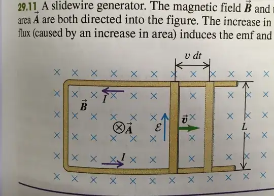
Edit 2: The Figure 29.11 shows for a bar moving to the right that the magnetic flux into the page increases. A counter-clockwise EMF ${\cal E}_{c-c}$ is needed to produce a counter-clockwise induced current which will produce an induced magnetic field that comes through the loop and out of the page and counter acts the increase in magnetic flux into the page caused by the bar moving to the right.

0

No the textbook is correct. Are you using Flemming's right hand rule?

Because according to the right hand rule if B (the magnetic field) is into the page and the motion of the wire is towards the left then the current will be pointing downwards. Relate that to part of the circuit parallel to the moving "arm PQ" and the circuit will be counter clockwise. :)

Here's an image of what the rule looks like: http://www.daido-electronics.co.jp/english/qa/magnet_lexicon/ha/images/ha13.gif

and I hoped this helped. Best of Luck, An IB Diploma Year II student

Fifi
  • 1
  • by that method you get current direction in PQ, not RS. – Shubham Sep 16 '15 at 16:18
  • OP already mentioned having tried using a Lorentz Force analysis with an answer consistent with the textbook. They are confused about how to analyze this situation under the Faraday's/Lenz' Law interpretation. – Trevor Kafka Sep 24 '18 at 00:59
0

Using LORENTZ FORCE negative charge accumulates At point P while point Q gets positively charged. Thus the current shown in the figure is correct one.

Remember that if you have a battery the conventional current (movement of positive charges) inside the battery flows from the negative terminal to the positive terminal.
The moving rod is a seat of emf and so the current flows from its negative end $P$ to its positive end $Q$ and then in the external circuit flows from the positive "terminal" $Q$ to the negative "terminal" $P$ .
So the (conventional) current direction should be shown to be clockwise and not anticlockwise as in your diagram.

Just to confirm the direction of the induced current; if the induced current is flowing downwards from $P$ to $Q$ and the magnetic field direction is into the screen then the force on the rod $PQ$ is to the right.
So the keep the rod moving at constant velocity an external force with a direction to the left needs to be applied to the rod.
The work done by the external force is the source of the electrical energy produced by the interaction of the moving rod with the magnetic field. This is Lenz's law in action in that the direction of the induced current is such as to oppose the motion (of the rod to the left) producing it.
If the induced current had been in the opposite direction ie upwards (from $Q$ to $P$) along the rod the interaction between the current and the magnetic field would have produced a force to the left.
In this case no external force is required to keep the rod moving and as electrical energy is generated this would contravene the law of conservation of energy.

Farcher
  • 95,680
0

Lorentz force is as follows: $$\mathbf F=q (\mathbf v×\mathbf B)$$

If negative charges ($q=$ -ve) are considered then the Lorentz force shall have to be in opposite direction (towards P not Q) $\Rightarrow$ current is from P to Q hence the Textbook diagram shows incorrect current flow direction.

  • Welcome to SE.Physics. Your late answer to this question does not add new information to previous answers. Moreover it contains an hypothesis on the sign of current carriers which is irrelevant for the answer (for the sign of currents one can conventionally assume positive carriers) and it is not not justified by the text of the problem. What if the circuit was made by a metallic conductor like Al where holes are the current carriers? – GiorgioP-DoomsdayClockIsAt-90 Jan 03 '20 at 08:57
-1

If the magnetic flux is decreasing in the into-the-page direction, the opposition to this change is an induced magnetic flux that is increasing in the into-the-page direction. Thus, the textbook is correct.

Additionally, your analysis of this situation using the Lorentz Force Law is perfectly correct, which is consistent with the textbook.

Trevor Kafka
  • 1,816
  • Comment by aymus bond: "Exactly that's what I mean, since there is a requirement to increase the flux into the plane (induced flux) the current for this to happen should be generated in the clockwise direction (according to lenz law). But the induced current shown in the textbook shows anti clockwise direction which will further reduce the already decreasing flux." Originally posted as an answer to this question: https://physics.stackexchange.com/a/430587/191954 –  Sep 24 '18 at 15:44
  • No, Lenz' law states that the current must create a magnetic field opposing the change (that I stated above). So, the current is counterclockwise. – Trevor Kafka Sep 24 '18 at 17:57
  • @ Trevor: Your understanding is incorrect. Faraday’s law, Lenz’ law and ${\bf F}= I_{\rm ind}{\bf L}\times {\bf B}$ all give the same answer. The induced current is in the clockwise direction. – Physics_Et_Al Sep 24 '18 at 19:11
  • Sorry, yes, you are completely correct. Not sure where I went wrong. Must have been using my left hand. facepalms with left hand apologies! – Trevor Kafka Sep 24 '18 at 19:48
  • @ Trevor: it's okay. We all make mistakes from time to time. – Physics_Et_Al Sep 24 '18 at 20:28
-1

I think the X's represent magnetic field going out of the page. If this is true, than the current will indeed be in the counter-clockwise direction, as the book says.

Shayol
  • 7